Fractal Architect 5 Help Index
Animation Segment Configurator
Applies to:FA 5
Reference: Animation Concepts
HowTo: Configurator HowTo
Animation Segment Configurator
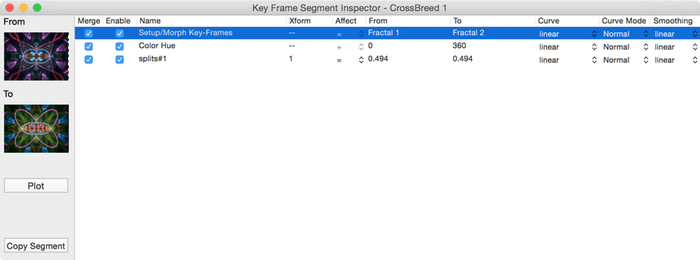
This is an Animation Segment Configurator view for a pair of morphed keyframes with a couple of other animations included.
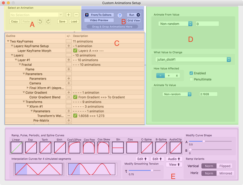
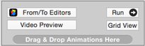
A. File Management and Utilities
B. Previews and From/To Editors
C. Property Selector
D. Property From/To Range Editor
E. Property Animation Curve Editor
Where is the Animation Configurator used?
- Triangle Editor - Custom Animations Button
- Cross Breeder - Custom Animations Button
- Super Variants Editor - Configure Variants Button
- Sequencer - Every segment - Edit Button
File Management and Utilities
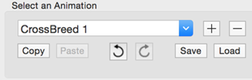
- Animation Selector
- Choose an animation segment to work on. (Not available in Sequencer).
- You can have multiple custom animation segments in the same fractal file.
- + Button
- Add a new animation segment. (Not available in Sequencer)
- - Button
- Remove this animation segment. (Not available in Sequencer)
- Copy
- Copy this animation segment to the clipboard.
- Paste
- Paste over this animation segment from the clipboard.
- Undo
- Undo the last change change.
- Redo
- Redo the last undone change.
- Save
- Save this animation segment to a file.
- Load
- Load an animation segment from a file.
Previews and From/To Editors
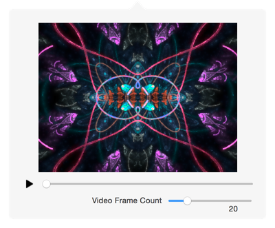
Video Preview
This windows allows you to see a video preview of the animation.
- ▶︎ Play Button
- Pressing this button will start the preview rendering. It will render Video Frame Count frames.
- Slider
- You can drag the slider with the mouse to see different rendered portions of the animation.
- Video Frame Count
- This slider sets the total number of video frames that playing the video will show.
Run Window
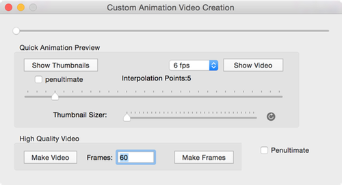
This window allows you to create a quick interpolation preview of the animation.
You can also make a High quality video using the Make Video or Make Frames buttons.
See: Quick-Spin for more information on how to use this window.
From / To Editors
The Configurator has a From/To Editors button that shows all keyframes and the From / To endpoint thumbnails.
You can edit the From / To Endpoints with Triangle/Color Gradient editor to setup the animation segment endpoints.
The Animation Configurator has 4 fractal thumbnails that you can modify.
Keyframe 1
From Endpoint
To Endpoint
Keyframe 2 (Only available for Cross-Breeder Custom Animations)
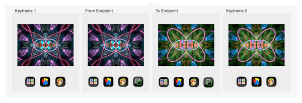
To define an animation segment, you would open 2 Triangle editor windows, one for the the From Endpoint and one for the To Endpoint.
When you CLOSE both editors, the differences between the two fractals will be used by the Animation configurator to create the equivalent Animation segment.
Grid View
There is a simplified Grid View that lets you see the Animation segment’s property animations.
Property Selector
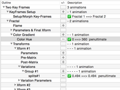
This is an outline view of all the categories in a fractal and the animateable properties they contain.
You click on a + button to add new properties to the animation segment.
You click on a - button to remove a property from the animation segment.
Property Categories in the Property Selector
The many properties are broken down into the hierarchy of categories shown here:
Two KeyFrames
Layerz KeyFrames Setup
Layer Keyframe Morph
Layerz
Layer #1
Fractal
Flame
Parameters
Parameters
Camera
Final Xform #1 (deprecated)
Parameters
Pre-Matrix
Post-Matrix
Variations
Group #1 …
Variation Parameters
Group #1 …
Color Gradient
Transforms
Transform #1 …
Parameters
Pre-Matrix
Post-Matrix
Variations
Group #1 …
Variation Parameters
Group #1 …
Final Transforms
Transform #1 …
ParametersPre-Matrix
Post-Matrix
Variations
Group #1 …
Variation Parameters
Group #1 …
The individual properties found in each catgory:
- Layerz Keyframes Setup
- Layer Keyframe Morph
- Fractal > Flame
- Blue Color Curve
- Green Color Curve
- Red Color Curve
- RGB Color Curve
- Highlight Power
- Looping Using Rotates Set
- Xaos Weights
- Fractal > Parameters > Parameters
- Background Color
- Brightness
- Fractal Origin - 2D spline path
- Fractal Origin - X Coordinate
- Fractal Origin - Y Coordinate
- Gamma
- Gamma Threshold
- Has Final Transform
- Vibrancy
- Viewport rotation
- Viewport rotation about point
- Viewport scale
- Viewport scale about point
- Viewport zoom
- Fractal > Parameters > Camera
- Camera Clip Points Behind
- Camera Depth-of-Field
- Camera Field-of-View
- Camera Fly-Thru - 3D spline path
- Camera Location X-Y-Z - 3D spline path
- Camera LookAt+Location - 3D spline paths
- Camera Orientation Yaw/Pitch/Roll
- Camera Ortho-to-Perspective Ramp
- Camera Ortho/Perspective Checkbox
- Camera Pitch
- Camera X Position
- Camera Y Position
- Camera Yaw
- Camera Z Offset
- Camera Z Position
- Fractal > Transforms > Xform #1 > Parameters
- Direct Color Weight
- Rotates
- Solo Flag
- Transform’s Color Index
- Transform’s Color Speed
- Transform’s Color Symmetry
- Transform’s Opacity
- Transform’s Weight
- Fractal > Transforms > Xform # > Pre-Matrix
- Pre Matrix - all Coefficients
- Pre Matrix - Rotate Scale Translate
- Fractal > Transforms > Xform # > Post-Matrix
- Post Matrix - all Coefficients
- Post Matrix - Rotate Scale Translate
- Fractal > Transforms > Xform # > Variations > Group
- All the variations in the current variation set.
- Fractal > Transforms > Xform # > Variation Parameters > Group
- All the variation parameters in the current variation set.
- Fractal > Parameters & Final Xform > Color Gradient
- Color Brightness
- Color Contrast
- Color Gradient Blend
- Color Hue
- Color Saturation
- Decrease Color Frequency
- Increase Color Frequency
- Rotate Colors
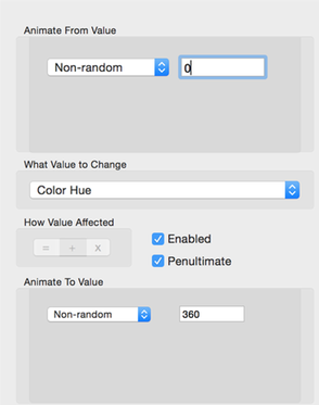
Property From/To Range Editor
This is the Range editor for the numeric property datatype.
- Animate From Value
- The from value.
- Animate To Value
- The to value.
- What Value To Change
- Selects the property to edit.
- How Value Affected
- = - Value is assigned to the property. (Overwrites property’s prior value.)
- + - Value is added to the current property value.
- * - Value is multiplied to the current property value.
- Enabled
- This property will be used in the animation. (You can disable this)
- Penultimate
- If checked, the final To calculated value is not used. This avoids repeated video frames.
How Property Values Are Calculated
The Input Animation Slider values vary between 0 and 1, with 0 being the far left and 1 the far right end of the slider.
The input value is modified by the Animation Curve, by finding the position of the input value on the X axis, and calculating for that X value what the Y value should be, based on the animation curve type. That calculated Y value is now the output of the Animation curve transfomation and becomes the effective animation amount (still in the range of 0 to 1).
Next, if chosen to be applied by the user, a smoothing interpolation is applied to the effective animation amount to “smooth” the effective animation amount. If not chosen, no change is made to the effective animation amount.
effAmount1 = animationCurve(inputAmount)
effAmount2 = smoothing(effAmount1)
Finally, depending on the Animation Affect selected, one of these equations is selected:
- Affect = (Assigned)
- output value = from + effAmount2 X (to - from)
- Affect + (Added to Original Value)
- output value = originalValue + effAmount2 X (to - from)
- Affect X (Multiplied to Original Value)
- output value = originalValue X effAmount2 X (to - from)
To create an animation the app will start the input animation amount at 0 and increasing it by steps up to 1. A video frame image is rendered for each incremental step.
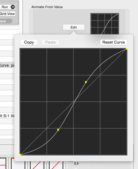
Property Animation Curve Editor
See: Animation Curves for more information.
Property Datatypes
Layerz Keyframe Morph Animation Config
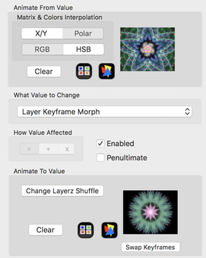
Morph animations cross-breed the from fractal with the to fractal. So the morph animation properties are similar to those found on the Cross-Breeder window.
Adding/Changing a Keyframe
- Copy a keyframe from elsewhere in the app, and paste it onto either the from or tokeyframes.
- OR drag a keyframe from elsewhere in the app and drop it onto either the from or tokeyframes.
- X/Y & Polar Matrix Interpolation
- Interpolate the Pre and Post transformation matrices using either linear or polar interpolation.
- RGB & HSB Color Gradient Interpolation
- Interpolate the Color Gradients with either RGB or HSB interpolation.
- Clear
- Remove the selected keyframe.
 Triangle Editor
- Open the Triangle Editor for the fractal.
 Open the Variants Editor
- Open the Variants editor to play with different random combinations.
- Change Layerz Shuffle
- Open the Layerz Morph Permutation editor.
- Re-order the rows in the editor to switch to a new permutation.
- Swap Keyframes
- Swap the From / To keyframes.
Keyframe Thumbnails Context Menu
- View Fractal Info
- Opens the Fractal Info window for this keyframe.
- View Fractal’s Source Text
- Open the XML source text for this keyframe.
- Make Fractal Variants
- Opens the Variants Editor for this keyframe.
- Copy
- Copies this keyframe to the clipboard.
- Paste
- Pastes over this keyframe with the keyframe on the clipboard.
See: Cross-Breeding Properties
Cross-Breed Shuffle Patterns
A morph takes the transforms from fractal 1 and transform from fractal 2 and blends them together.
The shuffle permutations are just different arrangements of which transform of fractal1 is blended with which transform of fractal2.
Here the permutation is 1, 2, 3:
| Flame 1 | Flame 2 | |
|---|---|---|
| Xform 1 | ===> | Xform 1 |
| Xform 2 | ===> | Xform 2 |
| Xform 3 | ===> | Xform 3 |
But there are other combinations. For example:
Here the permutation is 2, 3, 1.
| Flame 1 | Flame 2 | |
|---|---|---|
| Xform 1 | ===> | Xform 2 |
| Xform 2 | ===> | Xform 3 |
| Xform 3 | ===> | Xform 1 |
With 3 transforms, there are 6 different shuffle permutations.
The number of permutations for n transforms is: n! or n factorial.
n factorial is defined to be: n * (n - 1) * (n - 2) … 2, 1
So:
if n = 3, n! = 3 * 2 * 1 = 6
if n = 4, n! = 4 * 3 * 2 * 1 = 24
With the these two fractals each have 6 transforms to be morphed together. There are 720 different shuffle combinations where the right transform can be morphed with a transform on the left. The number of combinations is n factorial (6! = 720). If there are only
You will get a different morph animation with each shuffle combination. So in this example, you get 720 different morph animations from just 2 keyframes!
The default shuffle pattern is for the 1st left transform to be morphed to the 1st on the right, 2nd left to 2nd right, …
Layerz Permutation
Just like with transforms, when a fractal has more than one layer, you also have many layer permutations.
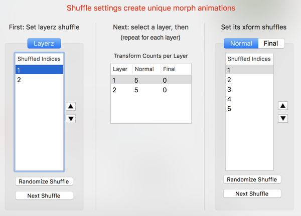
Layerz Permutations - How to Use
- Set layerz shuffle first.
- Then for each selected layer (select it on the left), set its transform shuffle.
- Since fractals can have multiple final transforms, remember to set this shuffle too.
How to Edit a Shuffle
First, set the crossbreeding amount slider close to 0.5. That way you can see middle of the animation.
These are the ways:
- Manually by selecting a shuffle index and moving it up or down the table, by pressing the Up and Down arrow buttons next to the table.
- Click the Randomize Shuffle button.
- Click the Next Shuffle button.
Numeric Property Value Animation’s Config
Numeric properties’ from/to values can be assigned in 4 ways, depending on the Popup Menu setting next to the From and To value text edit fields:
- Non-Random assignment
- Uniformly Random Floating Point Values
- Uniformly Random Integer Values
- Gaussian Random Floating Point Values
Non-Random Assignment
Modify the From and To values’ text edit fields to set the From and To values.
Uniformly Random Floating Point Values
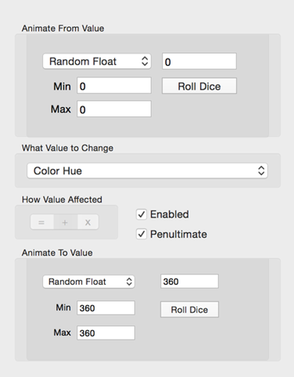
This configurator setting helps you select a random number to use for the from and to values.
Fill in the Min and Max text fields with numbers defining the random number range. Next, click the Roll Dice button to select a new uniform random number.
Uniformly Random Integer Values
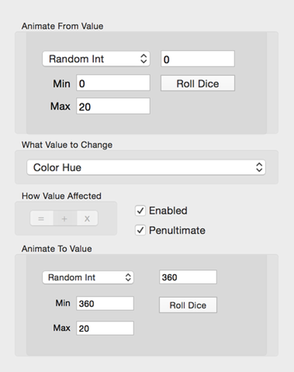
This configurator setting helps you select a random number to use for the from and to values.
Fill in the Min and Max text fields with numbers defining the random number range. Next, click the Roll Dice button to select a new uniform random number.
Gaussian Random Floating Point Values

This configurator setting helps you select a random number to use for the from and to values. It uses a Gaussian Bell-Shaped probability distribution.
Fill in the Mean and Sigma text fields with numbers defining the random number range. Next, click the Roll Dice button to select a new gaussian random number. The average random number will be the mean. And the random number range will be roughly in the range:
mean ± 2 × sigma
2D Point Property Value Animation Config
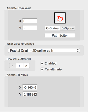
You set the from and to points’ X and Y values using the text fields.
Next, you can select either a 2D Catmull curve or 2D Bspline curve which specifies the path the point will follow in the animation. The Path Editor will open the curve editor.
See: 2D Bspline Curve Editor
See: 2D Catmull Curve Editor
3D Point Property ValueAnimation Config
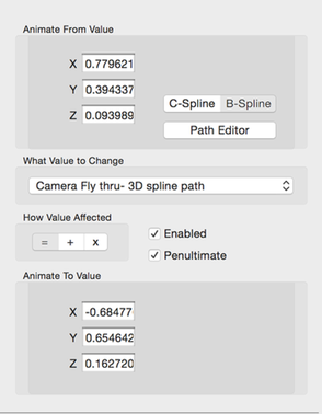
You set the from and to points’ X, Y and Z values using the text fields.
Next, you can select either a 3D Catmull curve or 3D Bspline curve which specifies the path the point will follow in the animation. The Path Editor will open the curve editor.
See: 3D Bspline Curve Editor
See: 3D Catmull Curve Editor
2D Transformation Matrix Animation Config
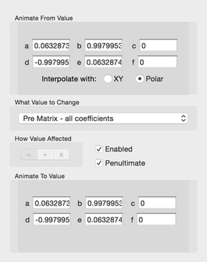
The matrix floating point values for both the from and to transformation matrices are specified.
You can choose to affect either the Pre or the Post matrices.
You can choose to interpolate the matrices using either linear or polar form interpolation.
2D Transformation Matrix Operations Animation Config
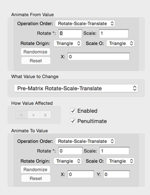
You specify a combination of rotation, scaling, and translation operations to applied to either the pre or post transformation matrices. These are similar to the operations you can apply to the transformations in the Triangle editor.
- Operation Order
- Choose the order in which the 3 matrix operations are applied.
- Rotate
- The rotation (in degrees) to apply.
- Rotate Origin
- Choose to rotate about either the triangle or world origins.
- Scale
- The scale factor to apply.
- Scale Origin
- Choose to scale about either the triangle or world origins.
- X
- Translate horizontally by this amount.
- Y
- Translate vertically by this amount.
- Randomize Button
- Randomize these settings.
- Reset Button
- Reset these settings to their default values.
You can choose to affect either the Pre or the Post matrices.
Color Gradient Animation Config
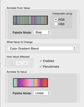
Use the Color Gradient editor to find other color gradients that look good with your fractal.
You can set the from and to color gradients by dragging a color gradient from the app’s Color Gradient editor and dropping it onto the gradient images.
- RGB & HSB Color Gradient Interpolation
- Interpolate the Color Gradients with either RGB or HSB interpolation.
- Palette Mode
- Select either a Step, Linear, or Smooth palette modes for the gradient.
Warning:
If the color stop count and color stop locations of the From and To gradients are NOT the same, the output colors of the From endpoint thumbnail will not match the Keyframe 1 thumbnail’s colors. Similarly the output colors of the To endpoint thumbnail will not match the Keyframe 2 thumbnail’s colors.
There is nothing wrong with mismatching color stops, it just makes it hard to predict the colors at the beginning and end.
Background Color Animation Config
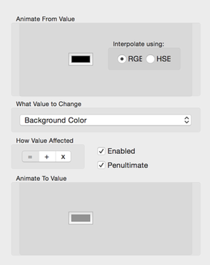
You set the from and to background colors. Click on the color wells to open the color picker.
- RGB & HSB Color Interpolation
- Interpolate the Color with either RGB or HSB interpolation.
Color Curve Animation Config
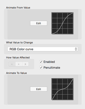
You set the from and to color curves.
Click on the appropriate Edit button to open the color curve editor.
Boolean Animation Config
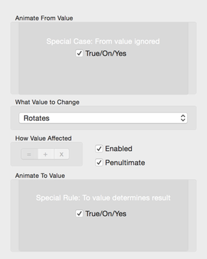
You set the from and to boolean values.
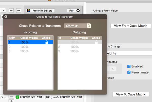
Xaos Animation Config
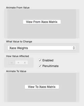
You set the from and to Xaos matrix values.
Click on the appropriate View Xaos Matrix button to open the Xaos Weights editor.
Rotate/Scale About Point Animation Config
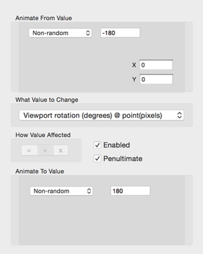
This configuration type applies to Rotation and Scaling the Viewport about a specific point.
It is the same as a Numeric value configuration except that you must specify the X and Y values for the viewport’s specific point .
Pitch/Yaw/Roll Animation Config
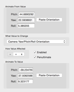
You set the 3 from and to 3D orientation angles:
- Pitch
- Yaw
- Roll
The animation engine will apply spherical interpolation to the 3 orientation angles.
You can copy the start/end 3D orientation angles from a 3D curve editor (see below) and paste it here.
Camera Location + LookAt Animation Config
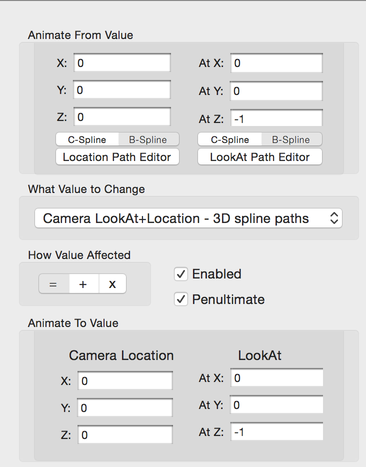
You set the 3 from and to camera location:
- Location X
- Location Y
- Location Z
You set the 3 from and to camera LookAt point:
- LookAt X
- LookAt Y
- LookAt Z
The animation engine will calculate the camera orientation using the vector from the camera location to the lookAt point.
There are two 3D spline curves - one for the camera location and one for the lookout point.
Commonly the lookAt point will remain fixed throughout the animation. Also another common pattern is for the camera location to be fixed and the lookAt point will move.
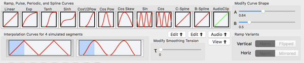
Interpolation Curve Controls
Whats a Ramp, Pulse, or Periodic Curve?
- Ramp
- Curve starts at the right keyframe and ends at the left keyframe.
- Pulse
- Curve starts at the right keyframe goes to the left keyframe, and then returns to right keyframe.
- Periodic
- Curve cycles back and forth between the keyframes.
Interpolation Curve Types
Curves affect the interpolated parameter values. The default Linear Ramp curve interpolates linearly from start to end parameter values.
The bottom of the curve box represents the left keyframe flame fractal. The top represents the right keyframe flame fractal.
- Linear Ramp (default)
- Not effected by A or B curve shape parameters.
- Exponential Ramp
- Affected by just A curve shape parameter.
- Tanh Ramp
- Affected by just A curve shape parameter.
- Sinh Ramp
- Affected by just A curve shape parameter.
- Cos Half-Power Ramp
- Affected by just A curve shape parameter.
- Cos Power Pulse
- Affected by just A curve shape parameter.
- Skewed Cos Power Pulse
- Affected by both A and B curve shape parameters.
- Sin Periodic
- Affected by both A and B curve shape parameters.
- Cos Periodic
- Affected by both A and B curve shape parameters.
- Catmull 2D Spline
- Use the Edit button to open the curve editor.
- See: 2D Catmull Rom Curves
- B-Spline 2D
- Use the Edit button to open the curve editor.
- See: 2D B-Spline Curves
- Audio Clip
- Use the Audio button to use a audio sound clip to create a curve.
- See: Audio Clip Curves
Smoothing Types
The affect of the Smoothing over 4 concatenated animation segments is shown in the graphic.
- None
- No smoothing is applied.
- Smooth
- Catmull-Rom spline smoothing. Tension (tau) parameter applies.
Ramp Variants
You can flip a curve upside-down or mirror it horizontally. This can be used to reverse the animation.
- Norm
- No change to animation order.
- Flipped
- Curve is flipped upside-down.
- Mirrored
Curve is mirrored horizontally.
Animation Curve Editors
The 2D and 3D animation paths are defined using the appropriate curve editors.
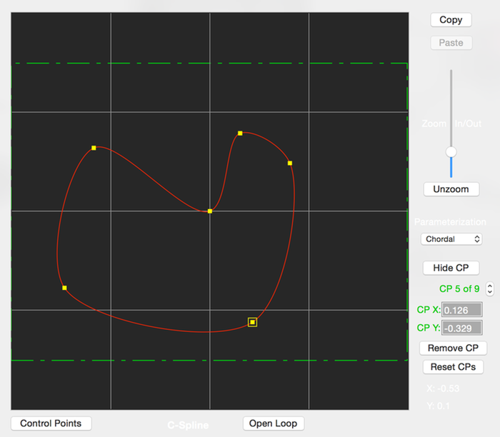
2D B-Spline Curves
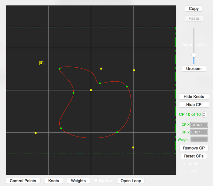
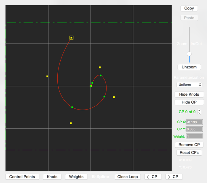
This editor creates 2D NURB or B-Spline curves. They can be either open or closed curves.
The placement of the curve’s control points determine the curve’s shape. Only the first and last control points are interpolated by the curve, the others just adjust the curve shape.
The plotted yellow squares are the control points, and the round green circles are the curve’s knot locations.
The green dashed lines represent the bounds of the fractal image and help you see where the control points are in relation to the fractal’s boundaries.
If the mouse is clicked close to an existing control point, it will be selected so you can drag it with the mouse to shape the curve. Otherwise, clicking elsewhere will add a new control point.
- Copy
- Copy the curve to the clipboard.
- Paste
- Paste the curve from the clipboard over this curve.
- Zoom slider
- Zoom in/out the plotted curve.
- If when zooming in and the curve moves out of view, use the graph’s horizontal and vertical scroll bars to move it back into view.
- Unzoom
- Reset the plotted curve to the default zoom.
- Parameterization
- Choose one of: uniform, centripedal, or chordal,
- Affects the curve’s “tightness”.
- Hide/Show Knots
- Hide/show the curve’s knots.
- Hide/Show CP
- Hide/show the curve’s control points.
- Control Point Selector
- Lets you edit the Control Point’s X-Y location and its weight.
- Remove CP
- Remove the selected control point.
- Reset CPs
- Reset the control points to a default linear curve.
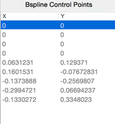
- Control Points
- Opens a popover showing the Control Points’ locations (readonly).
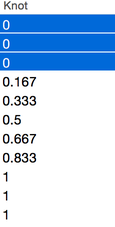
- Knots
- Opens a popover showing the Control Points’ knots (readonly).
- Weights
- Opens a popover showing the Control Points’ weights (editable).
- Open/Close Loop
- Change curve from closed to open form or vice versa.
- < CP
- Change position of control point in the control point list. Moves the control point down in the list.
- > CP
- Change position of control point in the control point list. Moves the control point up in the list.
2D Catmull Rom Curves
This editor creates 2D Catmull Rom curves. They can be either open or closed curves.
The placement of the curve’s control points determine the curve’s shape. All but the first and last points are interpolated by the curve.
The plotted yellow squares are the control points. The first and last control points are shown as green squares (they are not shown for closed catmull curves).
The green dashed lines represent the bounds of the fractal image and help you see where the control points are in relation to the fractal’s boundaries.
If the mouse is clicked close to an existing control point, it will be selected so you can drag it with the mouse to shape the curve. Otherwise, clicking elsewhere will add a new control point.
- Copy
- Copy the curve to the clipboard.
- Paste
- Paste the curve from the clipboard over this curve.
- Zoom slider
- Zoom in/out the plotted curve.
- If when zooming in and the curve moves out of view, use the graph’s horizontal and vertical scroll bars to move it back into view.
- Unzoom
- Reset the plotted curve to the default zoom.
- Parameterization
- Choose one of: uniform, centripedal, or chordal,
- Affects the curve’s “tightness”.
- Hide/Show CP
- Hide/show the curve’s control points.
- Control Point Selector
- Lets you edit the Control Point’s X-Y location.
- Remove CP
- Remove the selected control point.
- Reset CPs
- Reset the control points to a default linear curve.
- Control Points
- Opens a popover showing the Control Points’ locations (readonly).
- Open/Close Loop
- Change curve from closed to open form or vice versa.
- < CP
- Change position of control point in the control point list. Moves the control point down in the list.
- > CP
- Change position of control point in the control point list. Moves the control point up in the list.
3D B-Spline Curves
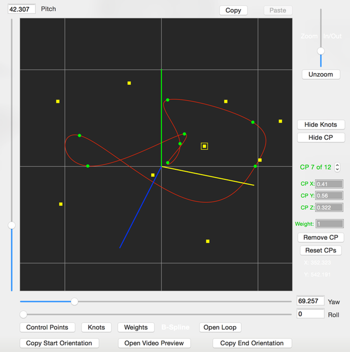
This editor creates 3D NURB or B-Spline curves. They can be either open or closed curves.
The placement of the curve’s control points determine the curve’s shape. Only the first and last control points are interpolated by the curve, the others just adjust the curve shape.
The plotted yellow squares are the control points, and the round green circles are the curve’s knot locations.
If the mouse is clicked close to an existing control point, it will be selected so you can drag it with the mouse to shape the curve. Otherwise, clicking elsewhere will add a new control point.
- Pitch
- Adjust’s the viewport’s pitch.
- (For viewing the 3D curve, changing this value makes it easier to see. Does not affect the actual 3D curve’s definition)
- Yaw
- Adjust’s the viewport’s yaw.
- (For viewing the 3D curve, changing this value makes it easier to see. Does not affect the actual 3D curve’s definition)
- Roll
- Adjust’s the viewport’s roll.
- (For viewing the 3D curve, changing this value makes it easier to see. Does not affect the actual 3D curve’s definition)
- Copy
- Copy the curve to the clipboard.
- Paste
- Paste the curve from the clipboard over this curve.
- Zoom slider
- Zoom in/out the plotted curve.
- If when zooming in and the curve moves out of view, use the graph’s horizontal and vertical scroll bars to move it back into view.
- Unzoom
- Reset the plotted curve to the default zoom.
- Parameterization
- Choose one of: uniform, centripedal, or chordal,
- Affects the curve’s “tightness”.
- Hide/Show Knots
- Hide/show the curve’s knots.
- Hide/Show CP
- Hide/show the curve’s control points.
- Control Point Selector
- Lets you edit the Control Point’s X-Y location and its weight.
- Remove CP
- Remove the selected control point.
- Reset CPs
- Reset the control points to a default linear curve.
- Control Points
- Opens a popover showing the Control Points’ locations (readonly).
- Knots
- Opens a popover showing the Control Points’ knots (readonly).
- Weights
- Opens a popover showing the Control Points’ weights (editable).
- Open/Close Loop
- Change curve from closed to open form or vice versa.
- < CP
- Change position of control point in the control point list. Moves the control point down in the list.
- > CP
- Change position of control point in the control point list. Moves the control point up in the list.
- Copy Start Orientation
- Copy the starting pitch/yaw/roll orientation to the clipboard.
- (So you can paste it onto a Pitch/Yaw/Roll Orientation animation.)
- Copy End Orientation
- Copy the starting pitch/yaw/roll orientation to the clipboard.
- (So you can paste it onto a Pitch/Yaw/Roll Orientation animation.)
- Open Video Preview
- Open’s the Video Preview so you can see what the affect of the 3D path is on the animation.
Design Note
In the Animation Sequencer, you may want to compose a sequence of 3 animation segments like this:
- Change 3D camera’s orientation
- Change the 3D camera’s fly-through path
- Change 3D camera’s orientation again
To get the first and last step’s camera orientations, use the Copy Start Orientation and Copy End Orientation buttons to put the correct orientation onto the clipboard. Then, paste the orientation onto the Camera Pitch/Yaw/Roll Orientation configuration (with the Paste Orientation button shown there).
3D Catmull Rom Curves
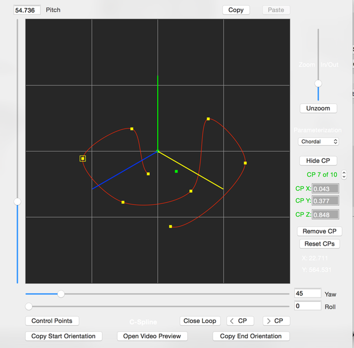
This editor creates 3D Catmull Rom curves. They can be either open or closed curves.
The placement of the curve’s control points determine the curve’s shape. All but the first and last points are interpolated by the curve.
The plotted yellow squares are the control points. The first and last control points are shown as green squares (they are not shown for closed catmull curves).
If the mouse is clicked close to an existing control point, it will be selected so you can drag it with the mouse to shape the curve. Otherwise, clicking elsewhere will add a new control point.
- Pitch
- Adjust’s the viewport’s pitch.
- (For viewing the 3D curve, changing this value makes it easier to see. Does not affect the actual 3D curve’s definition)
- Yaw
- Adjust’s the viewport’s yaw.
- (For viewing the 3D curve, changing this value makes it easier to see. Does not affect the actual 3D curve’s definition)
- Roll
- Adjust’s the viewport’s roll.
- (For viewing the 3D curve, changing this value makes it easier to see. Does not affect the actual 3D curve’s definition)
- Copy
- Copy the curve to the clipboard.
- Paste
- Paste the curve from the clipboard over this curve.
- Zoom slider
- Zoom in/out the plotted curve.
- If when zooming in and the curve moves out of view, use the graph’s horizontal and vertical scroll bars to move it back into view.
- Unzoom
- Reset the plotted curve to the default zoom.
- Parameterization
- Choose one of: uniform, centripedal, or chordal,
- Affects the curve’s “tightness”.
- Hide/Show CP
- Hide/show the curve’s control points.
- Control Point Selector
- Lets you edit the Control Point’s X-Y location.
- Remove CP
- Remove the selected control point.
- Reset CPs
- Reset the control points to a default linear curve.
- Control Points
- Opens a popover showing the Control Points’ locations (readonly).
- Open/Close Loop
- Change curve from closed to open form or vice versa.
- < CP
- Change position of control point in the control point list. Moves the control point down in the list.
- > CP
- Change position of control point in the control point list. Moves the control point up in the list.
- Copy Start Orientation
- Copy the starting pitch/yaw/roll orientation to the clipboard.
- (So you can paste it onto a Pitch/Yaw/Roll Orientation animation.)
- Copy End Orientation
- Copy the starting pitch/yaw/roll orientation to the clipboard.
- (So you can paste it onto a Pitch/Yaw/Roll Orientation animation.)
- Open Video Preview
- Open’s the Video Preview so you can see what the affect of the 3D path is on the animation.